Planning

The Planning tab is useful for office preparation to allow visual review of the subject property, identify open areas where target placement can be beneficial, and prepare before a site visit. If the Planning tab is grayed out, go back to the Project tab, verify that the correct project address is included, then select "Show" adjacent to Zip. This will display an overhead image of the address site.
Right click in the overhead view to select several options:
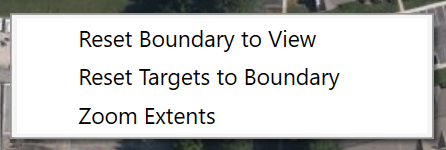
- Reset Boundary to View - will reset the boundary line
- Reset Targets to Boundary - will move all of the targets to an optimized location one-third inside the boundary
- Zoom Extents - zooms the view to the extents of the drawn boundary.
If no boundary is drawn, right click and select Reset Boundary to View to create a starting boundary.
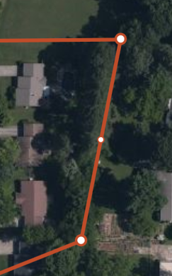
Clicking on any leg of the boundary will make the boundary line editable. Drag any highlighted circle to change the leg. Large circles denote vertices that can drag and move. Small circles denote line centers that will split to create new lines when clicked. To delete a leg, right click on the vertex.
Notice the Boundary Area dimension changing in the left pane to reflect the enclosed boundary size of the planned site. Units are controlled by the Settings dialog.
.
Once edits are completed press "Esc" or escape to confirm edits.
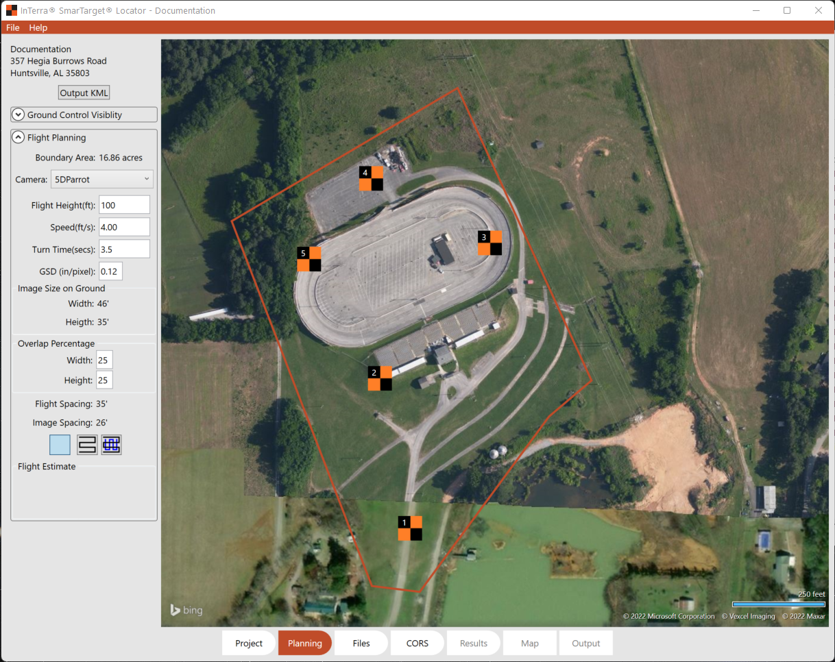
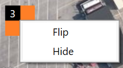
Use the pre-placed targets by clicking & dragging the target to put them approximately where they will be most useful in the field. This allows the user to save time with a high-level photo of the site and to plan in the office before going into the field. Toggles on the right side of the screen allow the user to disable targets not used. When placed there is an option to "Flip" the target, which allows white on black or orange on black depending on the terrain conditions.
Additionally, there is the option to save a .kml file for use in coordinating with customers and sharing with the team going to the field. And, some drone controllers can read the upload the .kml directly to start processing.
In the Flight Planning box are options for Camera, selected from the UAV.json file. Settings include planned drone flight height above the ground line, speed of flight, time of turn at each node, and the GSD or Ground Sample Distance as a function of pixel size. This option allows entry of a required GSD to calculate the Flight Height.
Output will show the Image size on the ground in project units.
Selecting the Width and Height of the desired overlap will allow for additional flight lines to shoot overlapping photography. A recommended value is 25%.
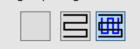
The Grid selection buttons allow the user to turn on and off the flight lines. The left box clears the flight lines, the middle box shows a two direction flight line, and the right box shows a 3D flight pattern. Flight lines are optimized to best cover the area of interest in least amount of time. The setting selected here affects the Output KML option.
Flight Estimate provides feedback for the estimated length of flight in project units, estimated number of photos to process, and an estimate of the Flight Time in minutes based on the above input parameters.
Now switch to the Files tab.